Concepts and terminology
The page describes concepts used in VTS.
There are two ways to onlook on VTS: either from the client side (interpreting existing data), or from the server side (composing or creating data). We call the first perspective analysis and the second perspective synthesis. Both perspectives are addressed in this document. For FE development, analytical concepts may suffice, however for work with backend, concepts both from analysis and synthesis are important.
Note
Notes like this will contain purely practical remarks for dealing with the concepts as a VTS beginner, without diving too much into the theory.
Analysis
Spatial Reference System (SRS)
To maintain consistency across the whole system, the SRSes in VTS are defined
in one central place in VTS Registry and then referenced by their
id wherever needed. In case of frontend, definitions of all needed SRSes
will be present in Map configuration.
Here is an example of SRS definitions with explanation below:
{
  "utm33n": {
      "comment": "Projected, UTM 33N",
      "srsDef": "+proj=utm +zone=33 +datum=WGS84 +no_defs",
      "type" : "projected",
  },
  "geographic-wgs84-egm96": {
      "comment": "Geodetic, WGS84 with EGM96 vertical (epsg:4326+5773)",
      "srsDef": "+proj=longlat +datum=WGS84 +geoidgrids=egm96_15.gtx +vunits=m +no_defs",
      "type" : "geographic",
      "geoidGrid": {
          "extents": {"ll": [-180,-90], "ur": [180,90]},
          "valueRange" : [-107, 85.4],
          "definition": "srs/geographic-wgs84-egm96/geoidgrid.jpg",
          "srsDefEllps": "+proj=longlat +datum=WGS84 +no_defs",
      }
  },
  "utm33n-va": {
      "comment": "Projected, UTM 33N, vertical adjusted",
      "srsDef": "+proj=utm +zone=33 +datum=WGS84 +geoidgrids=egm96_15.gtx +vunits=m +no_defs",
      "srsModifiers": [ "adjustVertical" ],
      "type" : "projected",
      "geoidGrid": {
          "extents": {"ll": [-2009979, 3000861], "ur": [2999421, 8260731]},
          "valueRange": [-17.6, 67.3],
          "definition": "srs/utm33n-va/geoidgrid.jpg",
          "srsDefEllps" : "+proj=utm +zone=33 +datum=WGS84 +no_defs"
      }
  }
}
Definition of geographic-wgs84 should be easily understandable to anyone
familiar with the `proj4 <https://trac.osgeo.org/proj/>`_ library. In fact, a
PROJ4 string in this case amounts to the entire definition. The type attribute
(which can take one of values projected, geographic or cartesian) is
in fact redundant, since these characteristics follow directly from the PROJ4
definition.
Definition of geographic-wgs84-egm96 is an example of a compound coordinate
system containing a combination of horizontal and vertical datum. It is fully
described by a PROJ4 string, yet the applicability of this definition relies on
availability of the EGM96 vertical datum grid. This grid is not directly
available to the web browser (for good reason, as it is 4 megabytes in size).
For usage in analytical contexts, SRSes with orthometric (gravity model based)
vertical datums are thus provided with a simplified mechanism defined in the
geoidGrid attribute: there is a definition of an ellipsoidal version of the
same SRS, a URL to a vertical datum grid, and georeferencing information for
that grid. Geoid grids used in this context are compressed and have lower
precision than datum grids used in synthesis; this is an acceptable trade-off
for their small size and usability in web rendering context (note that grid, not
pixel registration is used for georeferencing geoid grid extents for practical
reasons).
utm33n-va is the most complex definition. It is a coordinate system with well
known definition and a nonstandard modifier, named “adjustVertical”, applied to
it. This modifier is applicable to conformal SRSes and means that the Z
coordinate (which would represent orthometric height without modification) is
scaled proportionally to the local scale in XY plane to make the system
conformal in all three coordinates. There is no way to represent this modifier
in PROJ4, hence the SRS definition needs an extra attribute.
Note
Unless you choose to define your own reference frame, you should not need to define any new SRS.
Reference Frame
The concept of reference frames is of crucial importance in VTS design. In order to create and use 3D map data, we need answers to questions such as:
In which coordinate system (or more precisely spatial reference) are geometries within polygonal meshes and metatiles? When the user navigates the map, what is logic of motion? For example, what does pan motion mean, geometrically? When we rotate around and object, what is the axis of rotation? When we report spatial coordinates to the user, how do they relate to the coordinate system used for geometries? There is a tile hierarchy within the map. How is the map split into tiles? Is there a way to tell the physical extents of a tile with given indices on a given LOD?
For this reason, reference frames defines following:
- Physical spatial reference system, employed by mesh and free layer geometries
- Navigational spatial reference system, whose XY plane defines tangential movement (pan) and objective rotational movement (orbit) as movement along the plane and rotation around axis perpendicular to the plane, respectively; its Z component is employed by navigation tiles and it is the system used in positioning, both to define position and orientation
- Public spatial reference system, which is used when interfacing with the user (when informing user of current position in the map or of altitude or when handling user input)
- Spatial division, which defines physical extents of the model and extents of every tile on every LOD, either explicitly (for a specific tile) or by setting out a rule by which tiles are split into subtiles. In case the tile is explicitly defined, it defines unique SRS and extents which it (and its complete subtree) occupies in that SRS. This SRS is then used in metatile bounding boxes.
A reference frame is not the same thing as a spatial reference system (SRS), though the two are closely related. A reference frame defines multiple SRSes, and each of these serves a different purpose.
The nature of physical SRS defines two basic categories of reference frames. If the physical SRS is projected (such us UTM 33N or Web Mercator), we deal with a planar 3D map, or a projected reference frame. If the physical SRS is geocentric (such as `Geocentric WGS84 <http://spatialreference.org/ref/epsg/4978/>`_), we deal with a physical depiction of the planet (or another object), or a geocentric reference frame. This distinction is purely observational, since the algorithmic processing is precisely the same in both cases.
Here is an example of a simple hypothetical reference frame:
{
      "version" : 1,
      "id": "webmerc-unprojected",
      "description": "Earth, WGS84 spheroid based on Pseudo/Web Mercator",

      "model": {

          "physicalSrs": "geocentric-wgs84",
          "navigationSrs": "geographic-wgs84",
          "publicSrs": "geographic-wgs84-egm96"
      },

      "division": {

          "extents" : {
              "ll": [-7500000,-7500000,-7500000],
              "ur": [7500000,7500000,7500000] },

          "heightRange" : [-12500,9000],

          "nodes": [
              {
                  "id": { "lod": 0, "position": [0,0] },
                  "srs": "pseudomerc",
                  "extents": {
                      "ll": [-20037508.342789,-20037508.342789],
                      "ur": [20037508.342789,20037508.342789] },
                  "partitioning": "bisection"
              }
          ]
      },

      "parameters" : {
          "metaBinaryOrder" : 5
      }
}
With the corresponding SRS definitions:
{
  "geocentric-wgs84": {
      "comment": "Geocentric, WGS84 (epsg:4978)",
      "srsDef": "+proj=geocent +datum=WGS84 +units=m +no_defs",
      "type": "cartesian"
  },
  "geographic-wgs84": {
      "comment": "Geographic WGS84 (epsg:4326)",
      "srsDef": "+proj=longlat +datum=WGS84 +vunits=m +no_defs",
      "type" : "geographic"
  },
  "geographic-wgs84-egm96": {
      "comment": "Geodetic, WGS84 with EGM96 vertical (epsg:4326+5773)",
      "srsDef": "+proj=longlat +datum=WGS84 +geoidgrids=egm96_15.gtx +vunits=m +no_defs",
      "type" : "geographic",
      "geoidGrid": {
          "extents": {"ll": [-180,-90], "ur": [180,90]},
          "valueRange" : [-107, 85.4],
          "definition": "srs/geographic-wgs84-egm96/geoidgrid.jpg",
          "srsDefEllps": "+proj=longlat +datum=WGS84 +no_defs",
      }
  },
  "pseudomerc": {
      "comment": "Projected, Web/Pseudo Mecator (epsg:3857)",
      "srsDef": "+proj=merc +a=6378137 +b=6378137 +lat_ts=0.0 +lon_0=0.0 +x_0=0.0 +y_0=0 +k=1.0 +units=m +nadgrids=@null +wktext",
      "type": "projected",
      "periodicity" : { "type" : "X", "period": 40075016.685578 }
  }
}
What we get here is a geocentric system where all mesh and free layer geometries are represented in XYZ cartesian coordinates based on the WGS84 datum (with the SRS origin at the ellipsoid centre XY plane corresponding to the equator and X axis passing through zero longitude, with navigation controls based on the same ellipsoid (tangential pan motion and rotation around axis perpendicular to the ellipsoid surface), positioning given by the ellipsoid latitude and longitude, public UI readings based on WGS84/EGM96, spatial division into tiles based on Pseudo/Web Mercator. This is a full blown, physical model of the Earth between roughly 85.05112878°S and 85.05112878°N.
Not only these extents, but the tetranary hierarchy of tiles exactly corresponds to the one used by 2D maps on Here, Bing Maps, Google Maps, OSM and elsewhere, meaning that a tile at given lod/x-index/-yindex combination has exactly the same geographic extents in our reference frame as the Google Maps API tile with the same lod and x and y index combination. This trait means, among other things, that the public map services can play the role of external bound layers.
The working space is set to a cube centered at WGS84 center, with diameter of 15,000 kilometers - this even allows us to include some orbital phenomenons into the model if we want to.
Note that we could achieve virtually identical results with a slightly different reference frame. For example, our navigation SRS could use a spherical, as opposed to ellipsoidal model of Earth. This would make no difference to the user, and all of the above would still apply. The only difference would be that the internal content of navigation tiles would be different, containing spherical height as apposed to ellipsoidal height, and same would apply to positioning. And the axis of orbital motion would not point perpendicular to the (roughly ellipsoidal) Earth surface, but straight to Earth centre (or even more precisely, very close to Earth centre).
Helas, this simple model of Earth is missing polar caps. This is why we instead define the melown2015 reference frame with modified spatial division which includes the polar caps. Another interesting reference frame covering whole planet is a mars-qsc which represents Mars as a folded-out cube.
The most important thing to remember about reference frames is that there exists only one reference frame definition for each map configuration. Thus all surfaces, glues, bound and free layers within the same configuration need to stick to the same reference frame. The same principle, as we will see, applies to the concepts in synthesis. This is a basic requirement of homogeneity: combining map resources with different frames of reference is not possible, either resource has to be defined in both reference frames (for dynamically generated resources) or a conversion has to be performed.
Note
Whenever on Earth, use melown2015 reference frame. It contains WebMercator
subtree for bulk of the Earth and StereN and StereS subtrees for polar caps.
Due to geocentric physical system, it gives nice round Earth including polar
caps while most of existing WMTS and other services can be used directly with it
thanks to its WebMercator subtree.
The reasonable incentive for using or defining different reference frame is modeling of a different celestial object or the situation when many external services are available only in specific SRS. Then it may be reasonable to tailor the reference frame for that SRS.
Position
In VTS, the position is defined to accommodate the following requirements:
- independence of surface information and thus immediately usable
- orthogonality with respect to the vertical field of view (FOV), which is part of the position
- intuitive, and adaptable to multiple semantic contexts in which positioning is performed
The general position format is called an objective position. Simply said, it describes where is the point you look at and from where you look. Presuming you work in melown2015 reference frame with lat-long navigation SRS, the objective position may look like:
[ "obj", 14.401364, 50.090839, "fix", 295.77, -31, -47, 0, 613, 45.00 ]
where
- element 0 is string “obj”
- elements 1-2 are XY components of the center of orbit in navigation SRS
- element 3 is either “fix” or “float”
- element 4 is either Z component of the center of orbit in navigation SRS (if element 3 is “fix”) or its height AGL (if element 3 is “float”)
- elements 5-7 are NED based Euler angles (yaw, pitch, and roll) of the direction of view, measured at the center of orbit
- element 8 is vertical extent of camera view, measured at the center of orbit in physical SRS units
- element 9 is a vertical FOV, measured in degrees.
As a special case, the value of element 8 may be 0, indicating that the projection is orthographic.
A slightly less general position format, named subjective position, is defined as a similar 10-tuple:
[ "subj" ,14.404993 ,50.086954, "fix", 837.14, -31, -47, 0, 613, 45.00 ]
where
- element 0 is string “subj”
- elements 1-2 are XY components of the center of perspectivity in navigation SRS
- element 3 is either “fix” or “float”
- elements 4 is either Z component of the center of perspectivity in navigation SRS (if element 3 is “fix”) or its AGL (if element 3 is “float”)
- elements 5-7 are NED based Euler angles of the direction of view, measured at the center of perspectivity
- element 8 is vertical extent of camera view, measured at the center of orbit in physical SRS units
- element 9 is a vertical FOV, measured in degrees.
Under presumptions given, the example subjective and objective definitions are identical up to rounding errors. They define a view pointed at the Prague castle, oriented 31 degrees east of north and tilted 47 degrees downwards with observer at such distance from which a 613 meters long line perpendicular to the viewing direction is seen at 45 vertical degrees.
Fixed positions, both subjective and objective, meet the criterion of immediate usability (they directly translate to projection matrices in absence of surface information). There intuitiveness is limited by reliance on navigation altitude (which is typically geodetic height). Floating positions rely on intuitive concept of ground level altitude, which makes them surface dependent and not usable until surface geodetic altitude at given XY coordinates is available. Both positions meet the criterion of FOV orthogonality.
Objective positions are generic in the sense that they can describe all possible projection matrix definitions, including the orthographic projection. Subjective positions lack the ability to express orthographic projections as they are based on the center of perspectivity. Any subjective position may be converted into an objective position, and any objective position with a non-zero FOV may be converted into a subjective position. In a geographic navigation SRS this conversion is non-trivial, since Euler angles are based on local tangential planes and these planes differ in the center of perspective and in the center of orbit - this phenomenon is not manifested in the trivial example above, but it will become profound at larger scale orbits.
Attributions (credits)
The attributions in VTS are data driven, meaning that each resource will supply its own copyright information at data level. When browser displays a map, it will assemble all this information into a single attribution notice.
A claim of attribution may be associated with any VTS resource. An example follows:
{
  "melown":       { "id": 1, "notice": "{copy}{Y} Melown Technologies SE" },
  "basemap-at":   { "id": 2, "notice": "Data source: [http://www.basemap.at/ www.basemap.at]" },
  "seznamcz":     { "id": 3, "notice": "{copy} Seznam.cz, a.s." },
}
In VTS terminology, this is called an expanded claim of attribution (or expanded credits definition). Each attribution has a compulsory string id and numerical id. Both may be used for referencing outside the place where the credit was defined. String ids and numerical ids need to be unique across the entire map configuration regardless of where they appear, hence an expanded claim of attribution is in fact a combination of claim of attribution and at the same time its globally applicable definition. The notice is a template for the actual text presented to the user. It allows for wiki-like syntax for external links (as in case of basemap-at in the example above) and may contain the following macros (in curly braces):
{copy}expands into the copyright symbol U00A9{Y}expands into current year in four digits
A compact claim of attribution makes use only of attributions defined elsewhere and thus is not self-containing. The expanded claim above may be written as:
["citationtech", "basemap-at", "seznamcz"]
Finally, a specific claim of attribution is present within surface metatiles. It uses numerical id to identify the claimed attribution.
Scopes of attribution
There are two scopes under which the attribution may be displayed:
- Imagery: attributions from visible surfaces and bound layers
- Map data: attributions from visible free geodata layers
Attribution Powered by MELOWN is always included.
Suppose we are looking at Earth modeled using Viewfinder Panoramas DEM by Jonathan de Ferranti covered by Bing Maps aerial imagery and OSM based geodata drawn from Mapzen server. The complete attribution displayed will go as follows:
Imagery: ©2017 Microsoft Corporation, ©2005-16 Jonathan de Ferranti | Map Data: ©OpenStreetMap contributors, ©Mapzen | Powered by MELOWN
The more specific (higher LOD) attributions always go first. If there is not enough room to include all attributions, we put hyperlink with text “and others” after the first attribution, pointing to a tooltip containing all the attributions.
Surface
Surface a client side notion of tileset. More precisely, it is
- a geometrical definition of the modeled object’s surface,
- with optional textures and/or information on how to map external textures to object’s surface
The geometry of the surface is represented by polygonal mesh.
The client knows which surfaces to display from map configuration which contains URLs surface tiles, metatiles and navtiles (used for navigation above the terrain). If more overlapping surfaces are to be displayed, the visibility is determined by their fixed stacking order which comes from the storage stacking order on backend. The resulting combination of surfaces displayed can be viewed as one surface, usually referred to as virtual active surface.
Bound layer
Bound layers are tiled texture/imagery layers that are draped over surfaces. Map configuration tells the client which bound layers should be bound to a particular surface. Bound layers usually come from mapproxy but may also come completely external sources like TMS or WMTS services, if compatible with given reference frame. The actual draping of bound layer over surface happens on client, this allows e.g. switching the different bound layers for one surface without need to stream the surface data multiple times.
On the backend, binding of bound layer happens in storage view. First the layer has to be defined by giving it some id and pointing to boundlayer.json available from mapproxy:
{ // storage view
  "boundLayers": {
      "basemap-orthophoto": "https://maps.cdn.melown.com/tms/<group/<id>>/boundlayer.json",
      ...
  }
}
Then the layer is bound to one or more surfaces in view section:
{ // storage view
  "view": {
    "surfaces": {
      <surfaceId>: [<bound-layerId>, ..., "basemap-orthophoto"],
      ...
    }
  }
}
The last bound layer in the list wins, the last but one is displayed in places where the last is not available and so on.
To make the client draw the data from external service, the layer is simply defined in mapproxy using tms-raster-remote driver (see mapproxy resource definition). This allows for keeping all the bound layer definitions at mapproxy for overall consistency.
Bound layers usually metatiles which indicate which tiles are covered by underlaying data.
Free layer
Free layers are collections of three dimensional information capable of independent rendering. There are two facets to this independence: unlike bound layers, free layers do not require the active surface to determine their position. And unlike surfaces, they do not exclude other surfaces from rendering. As many free layers as needed may be rendered at a given position in the reference frame’s node hierarchy.
If a free layer is tiled, or organized in a tile hierarchy, it holds also an independent hierarchy of metatiles to achieve its independence on the active surface. In format and semantics, free layer metatiles are precisely identical to surface metatiles.
Currently there are two kinds of free layers:
- free geodata layer: Tiled or monolithic 3D vector data.
- free mesh layer: Arbitrary surface can be displayed as a free layer.
On the backend, the free layer is defined similarly as a bound layer in storage view:
{ // storage view
  "freeLayers" :
    {
      "streets" : "//cdn.melown.com/mario/proxy/melown2015/geodata/<group>/<id>/freelayer.json"
    }
}
Then it is used in view section:
{ // storage view
  "view": {
    "freeLayers": {
      "streets": {},
      ...,
      <surfaceId>: { "boundLayers": [<bound-layerId>, ...] },
    }
  }
}
Notice how surface can be used as a free layer simply by mentioning its id in view.freeLayers section. See cadastre tutorial for examples of free layer use.
Map configuration
Map configuration contains a all information the client needs to display given map/model. Although it does not contain any data that can be directly rendered, it contains URLs where the data can be retrieved and all needed accompanying configuration.
Contents of map configuration:
- Reference frame definition: all resources must be in this reference frame.
- SRS definitions: definitions of all SRSs used in reference frame.
- Bound and free layer definitions.
- Surface and glue definitions.
- View section: defining how surfaces, bound and free layers will be used together (actual composition can be modified with browser API).
- Default position.
- Other options.
The map configuration itself is not meant to be human-writable. Instead it is served by VTSD from storage view which is human-readable and -writable configuration. Alternatively, the map configuration can be served by VTSD for the whole storage or tileset or by mapproxy when http.enableBrowser is set to true in mapproxy configuration.
Synthesis
Tileset
Tileset is a tiled surface, set of meshes with metadata bound to one given Reference Frame. Meshes may or may not be textured. If not textured, meshes still have external texture coordinates to allow them being textured by e.g. Bound layer. Credit information (copyrights, attributions) is bound to the tileset.
For implementation reasons, there are more types of tilesets with the same interface. While practically indistinguishable, it is good to know about them for reference:
- plain tileset: basic tileset with all data stored within tileset location
- local tileset: tileset whose data are elsewhere on the disk, functionally behaves as symlink. Used to prevent copying large amounts of data while working with Storage
- remote tileset: tileset for which the tileindex is known but the tiles themselves are accessible at specified URL and are usually dynamically generated. Tilesets derived from DEMs and DSMs are usually remote.
- aggregated tileset: tileset acting as a proxy for part of storage or whole storage. Allows to handle groups of tilesets as a single entity.
Storage
Storage is a stack of tilesets sharing the same Reference Frame. Due to its stack nature it is always clear which tileset is on top if two or more tilesets overlap. Furthermore, the storage contains glues between it’s constituent tilesets enabling seamless visualization wherever two or more tilesets come into contact. Adding and removing tilesets into and from storage is done via vts commandline utility which takes care of the the glue generation.
Storage view
Storage view is human readable and writable configuration file which combines a
subset of tilesets from the storage,
bound layers and free layers from
mapproxy, credit definitions and other
options. When placed somewhere in the VTSD root (default path
/var/vts/store/ if installed as a part of the VTS Backend), VTSD is able to
serve the :ref: map-configuration based on the storage view at URL:
<url-to-storage-view>/mapConfig.json. Once you write the storage view, you
can check whether it is correct (produces valid mapConfig.json) by calling:
$ vts --map-config <path-to-storage-view>
Glue
A glue is synthetised Tileset from two or more original tilesets, to minimize data transfare and rendering time of final representation. Glues are pre-rendered on the server, so that client does not have to do the work multiple times.
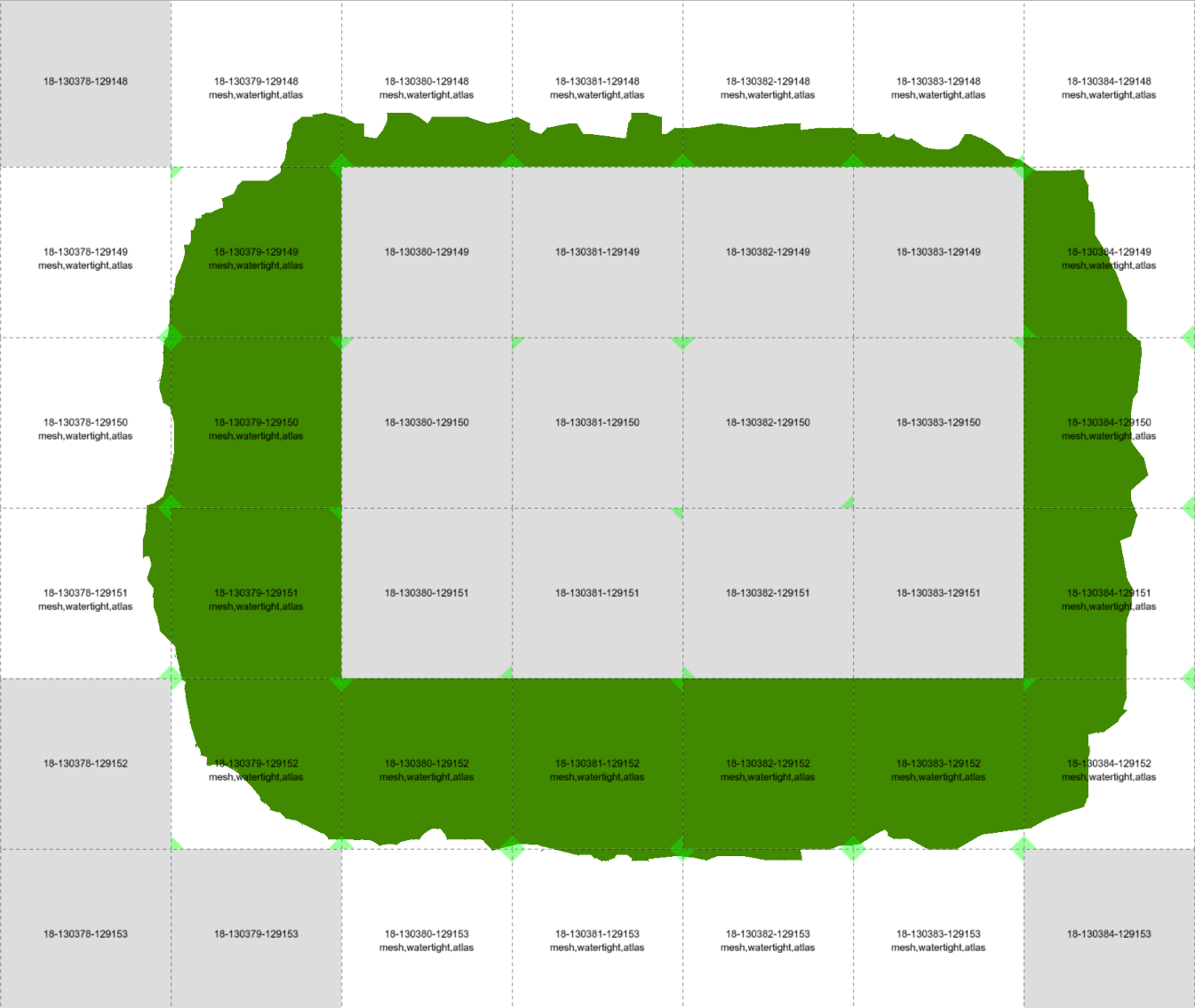
Green and white tiles are representing glue tiles between two tilesets, with representing different surfaces. Gray tiles “in the center” and gray tiles “on the permiter” are taken from original tilesets during final rendering.
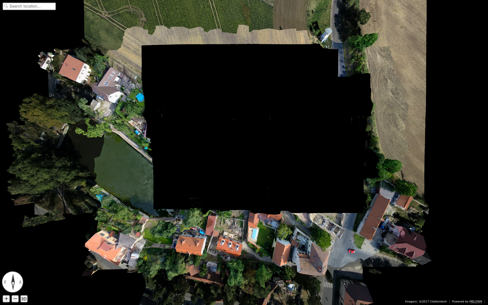
Final “glue mesh”, used for one Level of detail (LOD) to represent tiles, which are both covered by two tilesets.
Level of detail (LOD)
Level of detail. In traditional GIS this might be similar to zoom scale. It can be displayed as the “pyramid” in the upper picture.
Mask
Mask is special file, which can be used as standard binary mask, which “masks out” pixels out of region of interest.
Raster mask, source: http://pro.arcgis.com/en/pro-app/tool-reference/environment-settings/mask.htm
Metatile
The metatiles contain mainly:
- Data availability information - for which tiles the meshes, textures and other data are available and if there are further data deeper in the tile hierarchy.
- Geometry extents of underlying data - where in space are the meshes located.
- Coarseness information - size of the texture element.
Each metatile contains metainformation for many tiles (usually 1024) on the same LOD. Bound layer metatiles contain only data availability information.
The client first downloads some metatiles for each bound layer, free layer and surface. Based on current position and the information in metatiles, the client takes into account visibility and coarseness and decides for which tiles it will download meshes, textures, etc. and for which it will go deeper to get finer data.
Polygon mesh
Polygon mesh is collection of vertices, edges and faces that defines the shape of a polyhedral object in 3D computer graphics and solid modeling. The faces usually consist of triangles (triangle mesh), quadrilaterals, or other simple convex polygons, since this simplifies rendering, but may also be composed of more general concave polygons, or polygons with holes.
In VTS, meshes are used to construct final 3D surface, covered with Textures.
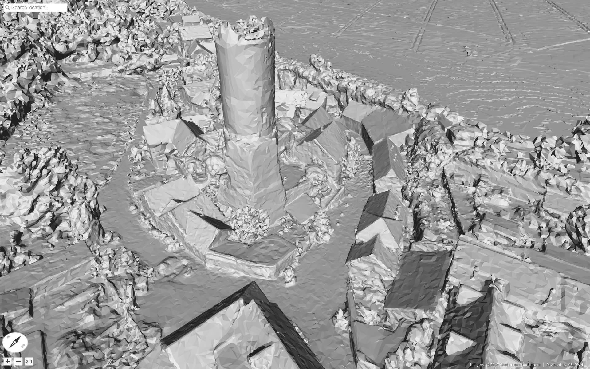
Flatshaded mesh, rendered as surface
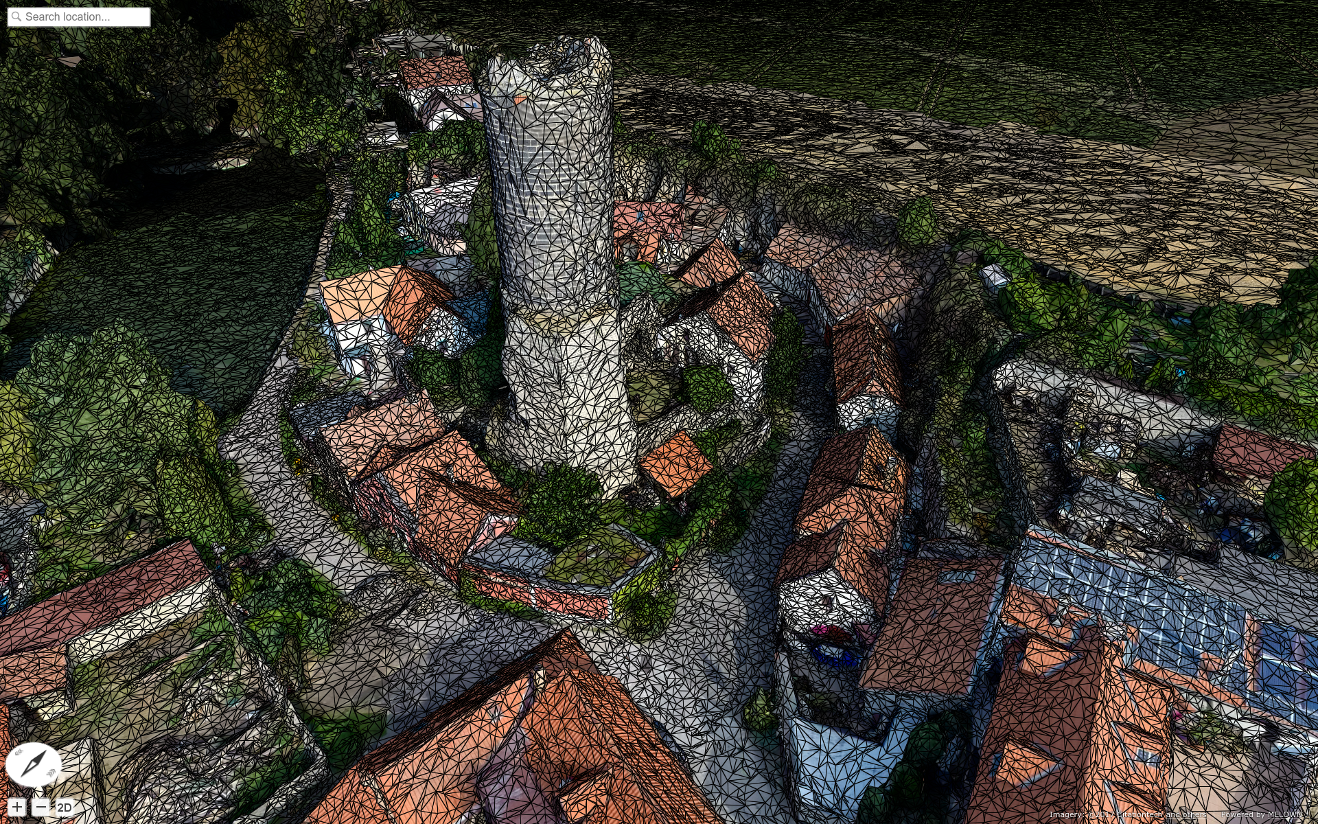
Image mesh filled with Textures
Texture
Texture map is a method for defining high frequency detail, surface texture, or color information on a computer-generated graphic or 3D model. In VTS, each surface tile contains also reference to metainformation-tile, which further contains reference to textures applied to the Polygon mesh. Textures are stored as simple JPEG images.
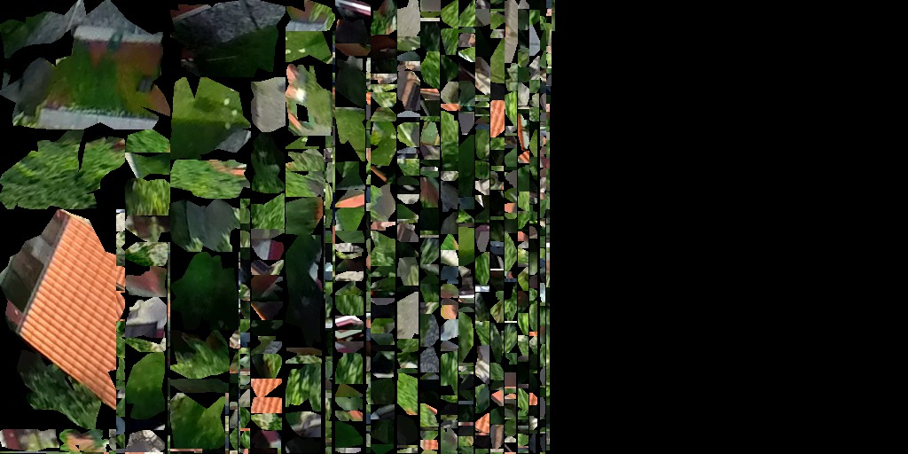
Image containing mesh textures